FixMyFD.com
Upgraded SSR
Upgraded SSR
This is built to order and normally takes less than 1 week to completed so please have patience while it’s being built. Each is tested before being shipped out.
This will fit direct in your current HR relay board frame so more from a mechanical relay system to a solid state. Also has replaceable relays if one just so happens to go bad.
all now come with the 3D printed bracket.
If your relay is not located behind the screen you are going to need an updated bracket from us. These are 3D printed and include 3M tape so you can stick it on your side wall next to the screen area.
Here are some details:
A triac is the device that is used in a Solid State Relay (SSR) – more on this is a second. The design also includes a Zero Cross detector.
When you want to control a AC device – you usually want to Start and Stop the device as the AC voltage goes thru zero volts. House AC voltage is normally expressed as 120 vac. This is actually the RMS (Root-Mean-Square) voltage with the actual Peak voltage at 140v. A circuit called a Zero-Cross (ZC) detector is used to signal when the AC wave goes thru zero volts. Below is an illustration of how a ZC works relative to the AC waveform. Note – “A” in the pic would be 140v and -140v.
The circuit implemented by HR is just reversed with the pulses going down instead of up.
This is a capture of the current HR firmware showing ZC on the bottom and the ON/OFF control of relay or SSR (Heating Trays only). The top wave form has a period of 12 hz – meaning they are turning a Tray Relay or SSR on and off 12 times a second. The amount of time the waveform is HI is how long the device under control is active – this is known as Pulse-Width Modulation (PWM) control. The waveform shown is HR just starting to heat up the trays – so the tray heaters are turned on for 84% of the time and turned off for 16%. as the trays get to temperature, the control might change and be on 20% and 80% off – the key note is that it is ALWAYS switching at 12 times a second.
HR has done a terrible job of implementing a PWM control of an AC device – they implemented it as if it was a DC device. Look at the ON part of the waveform – you can see that it turns ON just after the ZC signal says the AC is crossing zero volts – THAT is good! What is bad is the are just turning the power off to the tray heater when the PWM percentage has been met without any regard to ZC (Very Bad)! Notice where the top waveform goes OFF – relative to the ZC signal - the MIDDLE of the Positive ZC signal is which is at 140v.
The early cars (1960 Ford) I owned, all had distributors and points. Points needed to be replaced every so often because they would pit/stick and make the engine run terrible. Relays also have points. Pitting occurs when the power is being turned OFF after being ON. If you have 100v or more across those relay contacts – when they open – you get a spark and some metal is transferred from one contact to the other. After a while – the relay no longer functions.
The relays associated with the compressor and the vacuum pump will probable never fail because they are not turned off and on many times during the drying process. The tray heaters – another story – to put it in perspective – 12 times a sec * 60 seconds in a minute * 60 minutes in an hour = 43,200 off/on cycles per HOUR – THAT is why they failed!.
Think of a Triac as an AC switch. It has a control signal that will turn the switch on. Once on – the control can be removed and the switch will remain on until the AC goes thru zero volts – then it is off until commanded on again.
The 16 AC string controller I designed and shown above uses 16 triacs but no snubber circuits (why shortly). I control the lights’ brightness by deciding when on the AC positive or negative cycle to turn it on. If I turn it on just after ZC – then the light is the brightest it will be. If I turn it on just before reaching the next ZC – then it will be the dimmest. So I have 180 degrees of the AC wave form to decide how bright the light will be. I do this for EVERY cycle – there is a Positive cycle and a negative cycle – so I do dimming 120 times a second – this is also what the dimmers you buy at Home Depot do.
A simple triac circuit is great for Resistive loads – but NOT good for inductive loads. Motors have winding that have inductance. Inductance stores energy and when you attempt to turn OFF the power – the inductor/windings have to get rid of the their stored energy. If left unattended – it will blow out the triac. A snubber is a simple Resistor and capacitor (RC) circuit that routes the energy AROUND the triac so it’s not damaged during the turn OFF event. Snubbers are great when the load is a motor but when the load is resistive – you get “Leakage” current around the triac into the load.
When a freeze dryer uses a standard SSR (most all have snubbers) THAT leakage current goes to the tray heaters – and they start heating slightly even when the triac is OFF. I see this as an existing HR concern and a concern for the other manufacturers. I have NOT used a snubber circuit on MY relay board so no unwanted tray heating exists.
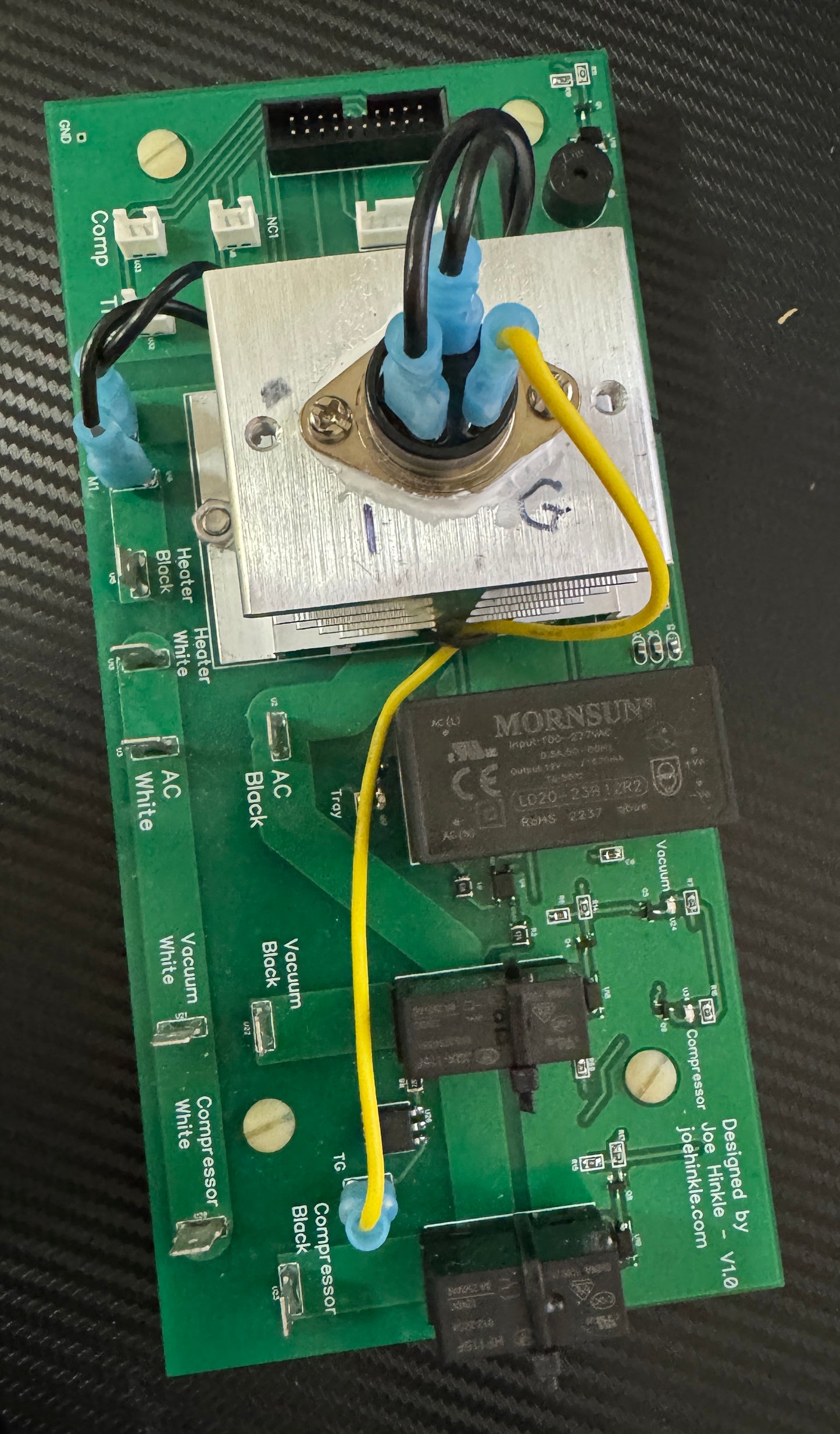
About this new board:
The board is about the same size as the HR board that came with my unit. Most PCBs are manufactured using 1oz copper for the top and bottom traces. I use 2oz copper which cost more but my traces don’t get as hot as they would using 1oz. I do not know what HR or the others guys use but they SHOULD also be using 2oz.
I have placed silicon bumpers on the under side of the board where each of the external wires are connected. This will prevent the PCB from cracking if someone pushes too hard installing the wiring.
I have clearly labeled White and Black connectors for the Tray Heater, Compressor, and Vacuum Pump wire connections. HR did NOT. If someone reversed the HOT and Neutral connections it might cause damage to the device it is powering.
I use nylon bolts to provide board attachment to HR’s metal bracket. They allow me to control the height the board sits above the metal bracket and also allows easier removal. NOTE: I have applied “lock tight” to the bolt and two nuts so that my control height stays fixed. Please don’t break the nuts loose.
NOTE: Please make sure to place the GREEN Grounding wire associated with the Compressor between the tray and the securing nut (closest to the compressor’s wiring connectors).
All the parts on the board that could fail over time – the Triac and the two Relays are removable and low cost replaceable. The relays each have sockets (not like HR where that are soldered in place) and each has a tie wrap to prevent the relay from coming loose over time.
There are RED leds that show when a device is being powered. Watch the Tray associated led blink every time it goes thru an off/on cycle (12 times a second).
The triac has a nice heat sink – bigger than it needs to be and I will look at using a smaller one when I run out of existing inventory. The triac has “heat paste” between it and the heatsink for better heat conduction. The current HR has no paste at all. They are mainly counting on the heatsink plug that is part of the SSR to do all the heat dissipation.
The temperature connections for the ambient probe (by the compressor) and the cable for the trays are clearly marked what their functions are – unlike HR – where you have to remember where each goes since they are NOT marked.
Couldn't load pickup availability
Share